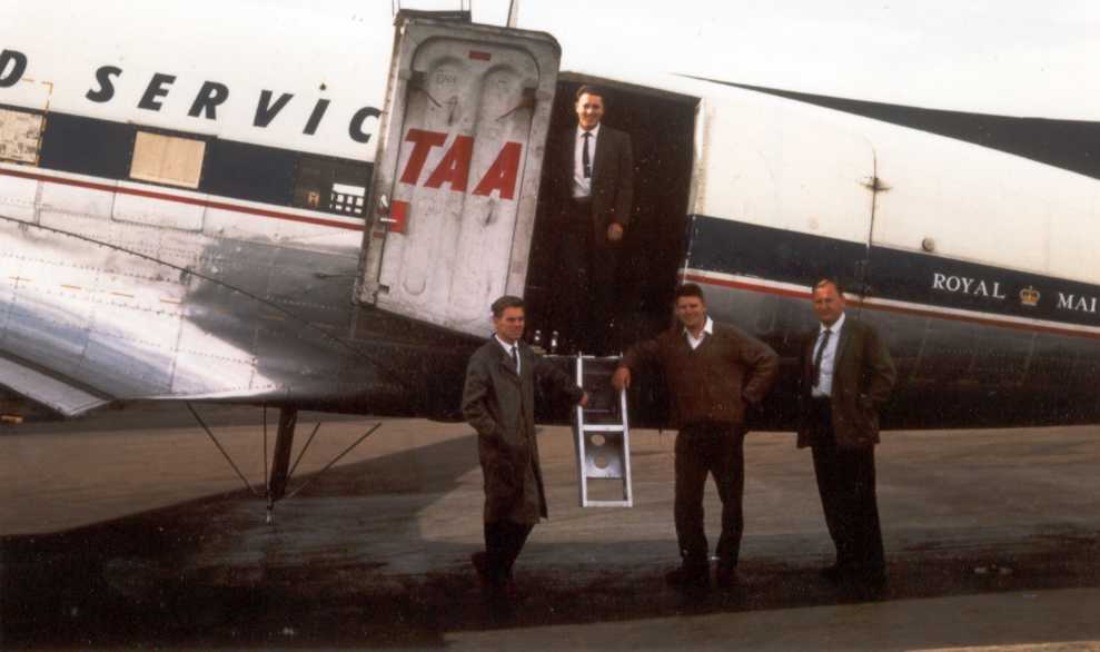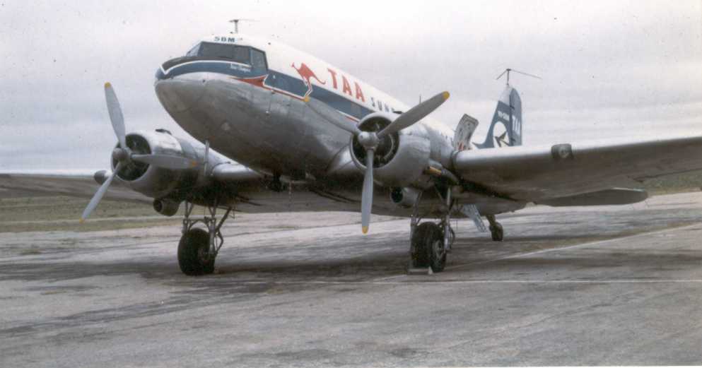
The aircraft on the tarmac
at
Nhill (Vic) airport during the
evaluation exercise.
AIRBORNE TV
Relay, 1963
by NEIL WAIN
The Royal Visit to Australia by the Queen and Duke of Edinburgh in February-March 1963 for the fiftieth anniversary of the naming of Canberra and other duties was considered of such importance that the PMG (Telstra) Research Laboratories decided to conduct an experiment to see whether TV coverage of the event could be relayed by 'satellite' to Adelaide which at the time was not connected to the East Coast terrestrial TV relay network.
Early in 1963 the PMG broad-band TV relay links on the eastern seaboard extended to the west only as far as Bendigo. It was thought that a TV relay to Adelaide would be possible using a strategically-placed aircraft as an airborne repeater. The idea was for the aircraft to carry transmission equipment capable of receiving the National TV station at Bendigo (Ch.1) and relaying the program on a vacant channel (Ch.5A) to the ABC TV transmitter site on Mt Lofty near Adelaide for re-transmission on ABS2. Twenty years earlier, a similar scheme was considered by the RAF during World War 2 to extend the range of 'Oboe', a navigational aid, deeper into enemy territory but the scheme was never put into practice.
The project required the TV relay equipment to be approximately midway between the two stations at an altitude sufficient to give a line-of-sight path to each site. A month or so before the Royal Visit was scheduled a team of PMG Research Laboratories personnel drawn from staff of the TV and Pulse Techniques Division, headed by Dr A. Seyler, and the Propagation Division headed by Mr. J. Reen, was formed to conduct tests using a chartered DC3 freighter from TAA's New Guinea Sunbird fleet, VH-SBM. The aircraft was equipped with a RCA BW-7A field intensity receiver and a simple quarter-wave whip antenna mounted under the belly of the aircraft for studying the signal strength of Ch.8's Bendigo transmission at various altitudes near Nhill, in Victoria. The Ch.8 frequency was used to expedite the test allowing a lightweight antenna of minimum dimensions to be quickly fitted to the aircraft, whereas Ch..1, being vertically polarised, would have required a substantial quarter-wave ground-plane antenna longer than one metre. Such an antenna was being designed for the exercise but was not ready for the evaluation test phase.
|
|
The aircraft on the tarmac
at |
Analysis of these tests, extrapolated to the proposed working frequencies, indicated that the proposal was feasible providing the equipment could be flown in an orbit of about one mile in diameter and between 10,000 and 15,000 ft above sea level at a point above Lake Albacutya near the Victorian town of Rainbow.
Early in January 1963 arrangements were made to equip Sunbird 'Sierra Bravo Mike' with two off-air Ch.1 receivers (main and standby), two small Ch.5A transmitters, monitoring equipment, antennas and the associated power supplies. The Ch.5A transmitter antenna was a vertically-polarised quarter-wave ground-plane fitted to the top of the tail fin. The Ch.I receiving antenna was also a vertically-polarised quarter-wave ground-plane in the ventral position that retracted into the fuselage for take-off and landing, an important extra item on the pilot's checklist.
|
|
The ground plane channel
1 |
To avoid the radiation pattern of the two antennas being affected by the fuselage and wings in a normal banked turn, the pilot was instructed to fly the orbit in a flat turn which required rudder and opposite aileron to virtually skid the aircraft around the circuit. I understand this is a dangerous manoeuvre in a tight turn as it could induce a spin which would take several thousand feet before an experienced DC3 pilot could recover control.
As previously mentioned, the optimum altitude for the reception and transmission of the TV program was somewhere between 10,000 and 15,000 feet, depending on meteorological conditions, which in an unpressurised cabin required the provision of individual oxygen masks for those on board. At these altitudes, even in a Mallee summer, it was rather chilly in the cavernous fuselage of a DC3 freighter which seems so much bigger inside than the passenger versions commonly flying the feeder networks at that time. With the wind whistling in through gaps around the ill-fitting dual rear doors and from the opening for the ventral antenna the cabin heaters were ineffectual. This, together with the constant roar of the Pratt and Whitney engines reverberating off the hollow fuselage, made conditions a little uncomfortable for the two PMG operators monitoring the performance of the system in the cargo bay of the aircraft.
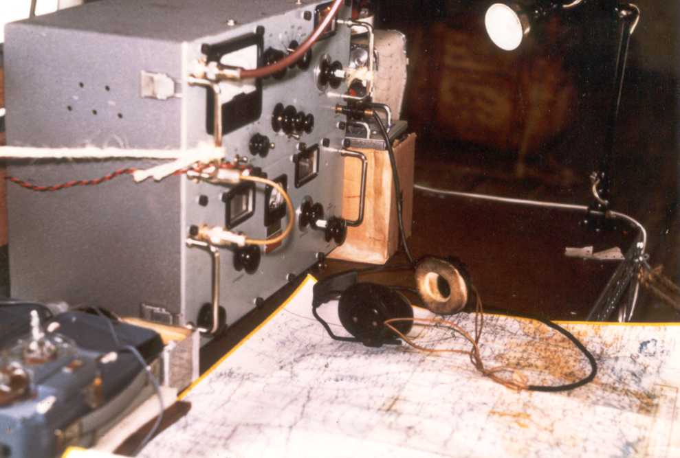
The main task of the PMG crew members was to predict the altitude at which the space wave from Ch.I was at a maxima and this was determined from the geometry of the paths and the estimated refractive index based on meteorological predictions for the area. The space wave is the vector resultant of direct and indirect (ground-reflected) rays at the receiving antenna. Its level varies from maxima to minima (fading) with changes to the height of or distance between the antennas (path geometry) or a change in tropospheric parameters (refractive index), all of which affect the relative path lengths and hence the phase relationship of the two rays. The BW-7A was used to monitor the received signal strength of Ch.1 during the orbit and, if necessary, the data was used to adjust the optimum altitude that was predicted from meteorological data prior to each mission. Having determined the appropriate altitude, the pilot was requested to seek permission to access the flight level concerned and fly the orbital pattern. Verification of the signal strength of the Ch.5A transmission was obtained from Adelaide via an on-board air-to-ground VHF transceiver and was used in the estimate for optimum altitude.
|
|
The BW7-A and plotting |
Of course the other important task of the PMG crew was to supervise the operation of the TV relay equipment as well as to assist the aircraft's flight engineer with control and maintenance of the on-board DC-to-AC power inverters and battery charging equipment.
The aircraft was flown by a captain and first officer and operated out of the Adelaide airport on most days for nearly two weeks. Each mission lasted up to five hours in the air with debriefing sessions on the ground after each flight. The relayed programs covered the Royal Visit activities in Sydney and Canberra as well as some test cricket between Australia and England.
From all reports, the relay was
well received by the Adelaide public but from a technical point of
view it suffered with occasional periods of poor signal-to-noise
ratio that would not meet CCIR transmission standards. No doubt the
relay was tolerated because it allowed Adelaide viewers a direct
broadcast of significant events on the east coast.
However, the
theory behind the technique was sound and it probably needed about a
10dB better fade margin to meet performance criteria.
I believe GTV9 also conducted a similar relay just prior to the PMG-ABC exercise to relay test cricket from Adelaide to Mt. William in the Grampians near the western-Victorian town of Stawell and then via TV OB links to Melbourne. I'm not aware of any report on their performance.
My recollection of personnel that were involved with the exercise is by no means complete but included the following:
PULSE TECHNIQUES DIVISION: Dr Albert J.Seyler, Head of Pulse Techniques. (originator); Jim Potter, TV engineer; Mike Subocz, TV engineer; Bob Smith, Technician.
RADIO PROPAGATION DIVISION: Jack H.Reen, Divisional Engineer, Radio Propagation Division; Otto Lobert, Group Engineer (propagation); Gavan Rosman and Bob Harvey, Propagation Engineers; Stan Barnard, Supervising Technician; Neil Wain, Senior Technician; Lyle Perkins, Technician
TAA: Captain Pumeroy
Reprinted by
permission from Radio Waves No. 65, July 1998 pp.14=16.
AIRBORNE
TV RELAY, 1963
by NEIL WAIN